Results 1 to 3 of 3

Thread: Nokia BB5,BB5+ Crystal IC Tricks and Guides

  1. #1
    GsmIndia.in Senior dpimani's Avatar
    Join Date
    Dec 2006
    Location
    DHARMAPURI.TAMIL NADU
    Age
    52
    Posts
    357

    Default Nokia BB5,BB5+ Crystal IC Tricks and Guides

    Nokia BB5,BB5+ Crystal IC Tricks and Guides


    NOKIA BB5, BB5+ EMI / ESD FILTER IC’S CONFIGURATION AND MODIFICATION WITH TROUBLESHOOTING PROCEDURES AND TRICKS..


    Q: What is a crystal IC?
    A: A Crystal IC is a small chips designed by Engineers to protect mobile phone devices, so that it cannot be damage by these this two harmful thing in Electronic circuits especially mobile phones..

    I'm talking about these two elements here>>

    Here's what I'm talking about....

    Electromagnetic interference (or EMI, also called radio frequency interference or RFI) is a disturbance that affects an electrical circuit due to either electromagnetic conduction or electromagnetic radiation emitted from an external source. [1] The disturbance may interrupt, obstruct, or otherwise degrade or limit the effective performance of the circuit. The source may be any object, artificial or natural, that carries rapidly changing electrical currents, such as an electrical circuit, the Sun or the Northern Lights.
    EMI can be intentionally used for radio jamming, as in some forms of electronic warfare, or can occur unintentionally, as a result of spurious emissions for example through intermodulation products, and the like. It frequently affects the reception of AM radio in urban areas. It can also affect cell phone, FM radio and television reception, although to a lesser extent.

    Electrostatic discharge (ESD) is the sudden and momentary electric current that flows between two objects at different electrical potentials caused by direct contact or induced by an electrostatic field. [1] The term is usually used in the electronics and other industries to describe momentary unwanted currents that may cause damage to electronic equipment.
    ESD is a serious issue in solid state electronics, such as integrated circuits. Integrated circuits are made from semiconductor materials such as silicon and insulating materials such as silicon dioxide. Either of these materials can suffer permanent damage when subjected to high voltages, as a result there are now a number of antistatic devices that help prevent static build up. (quote in wikipidia)


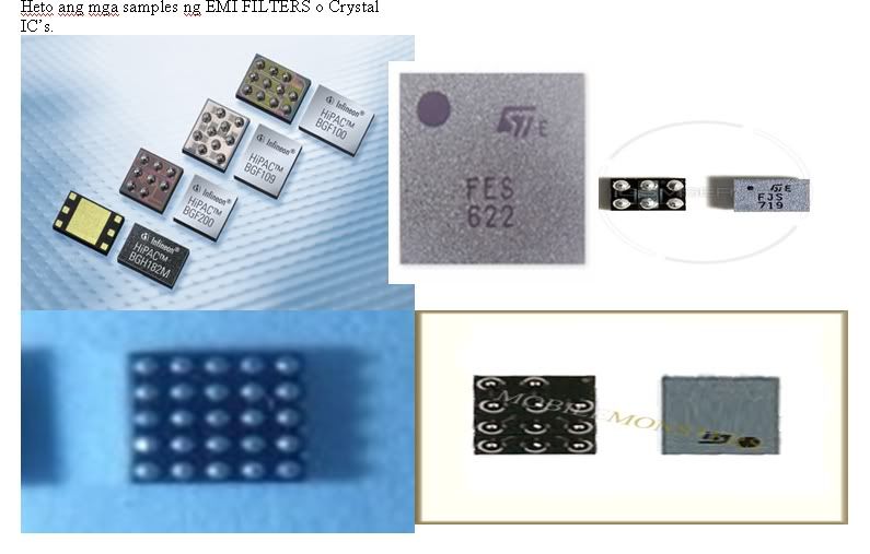
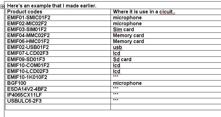
    Here's an Example picture of this tiny Chips...
    this tiny chips were most commonly damaged in terms of...
    a. display problems
    b. keypad problems
    c. microphone / audio problem
    d. sim-card problem
    e. memory card problem

    advisory some languges used in the images were Tagalog (Philippines Language) please be advice just please use google translator.


    Now here's where it is being used in Nokia circuit...

    and here the lists of all Nokia BB5 used this in a circuits...

    EMI FILTERS ON NOKIA BB5 PHONES


    EMI / ESD FILTERS

    3110c
    EMIF01-SMIC01F2
    EMIF03-SIM02F3
    EMIF04-MMC02F2
    EMIF07-LCD02F3
    EMIF10-LCD02F3
    3250
    EMIF03-SIM02F2
    EMIF04-MMC02F2
    EMIF10-COM01F2
    3500c
    EMIF01-SMIC01F2
    EMIF03-SIM02F3
    EMIF04-MMC02F2
    EMIF07-LCD02F3
    EMIF10-LCD02F3
    5220XM

    5300/5200
    EMIF01-SMIC01F2
    EMIF03-SIM02F2
    EMIF04-MMC02F2
    EMIF10-COM01F2
    5310X
    EMIF06-SD02F3
    EMIF07-LCD02F3
    5320

    5500
    EMIF01-SMIC01F2
    EMIF03-SIM02F2
    EMIF04-MMC02F2
    EMIF10-COM01F2
    5610
    EMIF02-MIC02F3
    EMIF03-SIM02F2
    EMIF06-HMC01F2
    EMIF10-LCD02F3
    6085
    EMIF03-SIM02F2
    6125
    EMIF03-SIM02F2
    6131
    EMIF03-SIM02F2
    EMIF04-MMC02F2
    EMIF10-COM01F2
    6233
    EMIF03-SIM02F2
    EMIF04-MMC02F2
    EMIF10-COM01F2
    6270
    EMIF03-SIM02F2
    EMIF04-MMC02F2
    EMIF10-COM01F2

    6280/6288
    EMIF03-SIM02F2
    EMIF04-MMC02F2
    EMIF10-COM01F2
    6300
    EMIF10-LCD02F3
    6500s
    EMIF06-HMC01F2
    EMIF10-LCD02F3
    6630
    EMIF03-SIM02F2
    EMIF04-MMC02F2
    EMIF10-COM01F2
    6680
    EMIF03-SIM02F2
    EMIF10-COM01F2
    7370
    EMIF03-SIM02F2
    EMIF10-COM01F2
    7373
    EMIF03-SIM02F2
    E50
    EMIF10-COM01F2
    E60
    EMIF01-SMIC01F2
    EMIF03-SIM02F2
    EMIF10-1K010F2
    EMIF10-COM01F2

    N70
    EMIF01-SMIC01F2
    EMIF02-MIC02F2
    EMIF03-SIM01F2
    EMIF04-MMC02F2
    EMIF10-COM01F2
    N73
    EMIF06-HMC01F2
    EMIF10-COM01F2
    N76
    EMIF02-USB01F2
    EMIF10-LCD02F3
    N78
    EMIF07-LCD02F3
    N80
    EMIF10-COM01F2
    N82
    EMIF02-USB01F2
    EMIF10-COM01F2
    N91

    N93
    EMIF02-USB02F2
    N95
    EMIF09-SD01F3

  2. #2
    GsmIndia Editor Sr. jayantassam's Avatar
    Join Date
    Jun 2010
    Location
    india
    Age
    54
    Posts
    819

    Thumbs up

    Now, Lets explore them one by one...
    EMIF01-SMIC01 - used in bb5 phones that also uses RETU 3.02 Power IC like N70 and etc.
    I’m talking about this IC below.


    here's the bump configuration...


    This is how it works:

    * when making a call, a voltage or current from RETU IC terminal H1 will draw the line of R2101(resistor) to IC terminal A2 to supply the microphone’s b+ terminal.
    * once the supply voltage is entered, the microphone is now on active state., once in active state. The microphone reacts into a high fidelity level, in short, meaning, it’s sensitive to catch audible sounds. But, this circuit was designed to enduced noise
    * when a sounds is catch up, the microphone now then feeds back the audible sounds to RETU IC terminal K1(+) and J3 (-) to amplify it and feed to RF during transmission.
    * it works like a mic pre-amp(pre-amplifier)

    A microphone preamp is a preamplifier used to amplify a microphone's low output voltage to a stronger, more usable level. A microphone preamp must provide stable gain for small signals without being sensitive to induced noise from cabling and without distorting large amplitude signals.Most microphones must be used in conjunction with a microphone preamp to function properly.

    Q: can we check this IC if suspected went wrong or damaged?
    A: Yes. If you're that so keen... like me..

    Follow the procedures below:

    1.1. Remove the IC . Set your Multitester to X1k, connect the probe sa A2 at C3. here you are about to check the voltage supply line to the positive of MIC terminal. Normal reading in this area is 2.3k (+/-).
    Without reading here, the IC is open or faulty…

    2. connect the probe sa B1 at C3, normal resistance reading here is 2.2k

    (+/-) Without reading here the IC is open or faulty.


    3. connect the probe sa C1 at C3, normal resistance reading here is 4.5k (+/-).
    Without reading here the IC is open or faulty.
    4. now, set the multitester to X1 and check the grounding terminals from B2,B3 and C2 to terminal A2 B+ line
    B1 at C3. there should be no reading happens here, if there is. it indicates the IC is shorted or busted...


    Modifying or Jumper Techniques if you have no replacement available...


    ================================================== ================================================== ================================================== ========================

    BGF100 - EMI MIC FILTER IC

    BGF100-(EMI FILTER) Mic IC - Used in most BB5 phone that also used RETU 3.02 Audio / UI IC’s..this kind of IC was designed with differential microphone filter.
    This one works same as EMIF01-SMIC01. but this one designed as a differential-meaning both positive at negative lines of the microphone were both filtered. the negative side of the microphone is not directly connected to ground…
    . see picture below:


    Here is an example of BGF100 in NOKIA BB5 mic internal cicuit..


    BGF100 in Mic Internal Circuit..
    Now, here how it works, when making a call a voltage / current will draw the line of R211 to supply the
    Vcc (B+ terminal) A2 of the said IC to turn the microphone into active state. Once in active state the phone is now on capable of catching sounds and then feed it to the lines of B4 to B1, C4 to C1 and then send to C2100 and C2101 to purify the audio signal and send to RETU IC to amplify during transmission.


    BGF100 in Mic External CircuitWhen plugging an external headset the terminal or bump A4
    Will react and send small signal to RETU to release the voltage/current of 2.1V to supply
    the IC. And then the voltage / current will draw the line of R211 to supply the
    Vcc (B+ terminal) A2 of the said IC to turn the microphone into active state. Once in active state the phone is now on capable of catching sounds and then feed it to the lines of B4 to B1, C4 to C1 and then send to C2100 and C2101 to purify the audio signal and send to RETU IC to amplify during transmission.


    (all credit goes to original poster)

    thanks
    js

  3. #3
    GsmIndia.in Active Teen hmishra421's Avatar
    Join Date
    May 2011
    Location
    bhopal
    Age
    33
    Posts
    225

    Default

    Thanks for this ,its really help me
    ALSO TELL ABOUT LCD IC

Thread Information

Users Browsing this Thread

There are currently 1 users browsing this thread. (0 members and 1 guests)

Similar Threads

  1. For Beginners Complets Repair Tutorials
    By =GsM_Angel= in forum Beginners Lounge
    Replies: 25
    Last Post: 07-07-2012, 11:33 AM

Tags for this Thread

Bookmarks

Posting Permissions

  • You may not post new threads
  • You may not post replies
  • You may not post attachments
  • You may not edit your posts
  •